Manufacturing a reliable round micro tensile specimen is not simply a matter of scaling down a conventional tensile bar. When only a very small material volume is available, or when a precisely defined local region must be tested, specimen preparation becomes part of the measurement strategy itself.
The microsample approach therefore treats preparation as an integrated process chain: the relevant material volume is selected and positioned where required, the desired rotationally symmetric specimen contour is generated by controlled rotational grinding, and geometry and surface condition are inspected throughout the preparation process. Polishing can be added as an optional final preparation step.
Starting from Different Customer Geometries
The starting material does not need to have a standardized geometry. Round micro tensile specimens can be prepared from different customer-specific starting conditions, including cylindrical, rectangular and irregular geometries as well as material with inclined surfaces.
Depending on the investigation, the starting material may be a complete component, a pre-cut section, a fragment or fractured part, a small component, or a metallographically prepared sample. The preparation route is therefore adapted to the available geometry, material condition and investigation objective.
For site-specific preparation, the relevant material volume can be selected within the source material and the later specimen axis positioned accordingly.
Site-Specific Positioning of the Specimen
For site-specific testing, the decisive question is which material volume will actually be located in the tensile section. A region of interest (ROI) can therefore be defined within the source component together with the intended specimen axis and a suitable reference.
The later tensile and rotation axis is deliberately aligned relative to the material region to be investigated. Suitable optically detectable or geometrical features can be used as references for positioning. The selected position and orientation are then transferred to the preparation setup so that the material volume subsequently located in the tensile section corresponds to the intended region of the source material.
Dedicated positioning, holding and transfer systems can be used where required to preserve the defined position and orientation during preparation and handling.
Source: microsample original graphic.
Generating the Round Tensile Section by Rotational Grinding
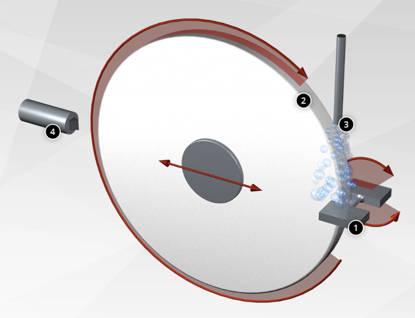
The core of the microsample preparation method is controlled rotational grinding. During preparation, the specimen or source material rotates about the selected longitudinal axis while a profiled grinding wheel removes material around the intended tensile section.
The grinding wheel is dressed to a defined profile representing the negative contour of the required specimen geometry. The combination of specimen rotation and the profiled grinding wheel generates a contour that is rotationally symmetric about the specimen axis.
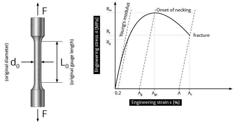
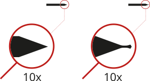
A typical micro tensile specimen consists of a cylindrical gauge section, adjoining transition radii and head regions required for the subsequent tensile test. However, the preparation process is not limited to one fixed tensile specimen geometry.
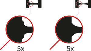
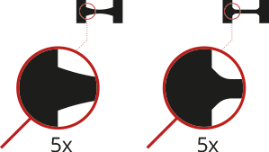
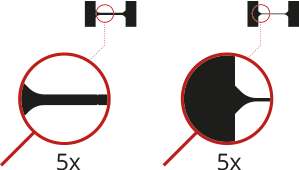
Different customer-specific contours can be produced, provided that the machined contour is rotationally symmetric about the specimen axis. The grinding-wheel profile can therefore be adapted to the required specimen geometry.
The examples illustrate different rotationally symmetric specimen contours that can be generated by adapting the grinding-wheel profile.
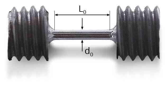
Source: Combination of microsample original graphics.
 |
 |
 |
 |
 |
The microsample Rotational Grinding Principle
The defining feature of the microsample preparation method is that the required rotationally symmetric specimen contour is generated through the combination of specimen rotation and a correspondingly profiled grinding wheel.
The rotational grinding process combines the micro tensile specimen (1), the grinding unit (2), the liquid cooling system (3) and the wheel dressing diamond (4). During preparation, the specimen (1) rotates about its longitudinal axis while the profiled grinding wheel of the grinding unit (2) progressively removes material and generates the rotationally symmetric contour. The grinding wheel is dressed to a defined profile by the wheel dressing diamond (4), with the profile representing the negative contour of the required specimen geometry. Liquid cooling (3) is applied during grinding to reduce heat input.
Material-adapted abrasives and low feed rates are used with the objective of reducing grinding forces and keeping preparation-induced influence on the remaining material as low as practicable.
The grinding operation can be interrupted before the final dimensions are reached. The specimen geometry can then be inspected and, where required, the grinding-wheel contour or process parameters can be adjusted before preparation continues.
microsample original graphic.
An Iterative, Material-Specific Preparation Process
Micro tensile specimen preparation is not necessarily a one-pass operation. Grinding, inspection and adjustment can be repeated while the specimen remains in the controlled preparation setup.
Grinding → optical inspection → adjustment if required → further grinding → optional polishing → final inspection
This iterative approach allows the preparation process to be adapted to the material, required specimen dimensions and desired contour rather than treating specimen fabrication as a fixed sequence.
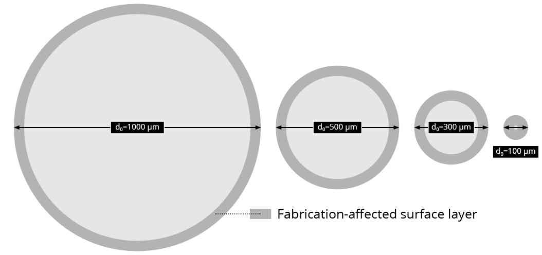
With the microsample preparation method, round micro tensile specimens can be prepared with diameters ranging from approximately 50 µm to a few millimetres, depending on the specific preparation task. The standard preparation range is approximately 100–1000 µm. Specimens below 100 µm or above 1000 µm require task-specific assessment, and approximately 50 µm should not be interpreted as a generally achievable minimum diameter.
The meaningful specimen size can also be limited by the material and investigation objective. Microstructural features such as grain size, inclusions, pores or phase distributions may become increasingly relevant as the investigated material volume decreases.
Surface Condition after Grinding and Optional Polishing
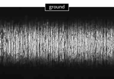
Grinding is the primary shaping process. Due to the rotation of the specimen during preparation, the resulting grinding marks are oriented circumferentially around the round tensile section.
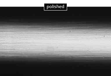
For some materials and testing objectives, the controlled ground surface can already represent the required final specimen condition. Polishing is therefore not a mandatory part of the preparation process.
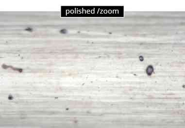
Where required, mechanical-metallographic polishing can be performed after grinding using progressively finer preparation media. In the tensile section and transition regions, polishing is performed parallel to the tensile axis and therefore perpendicular to the circumferential grinding direction.
The objective is to achieve the surface condition required for the intended investigation while keeping preparation-induced influence on the remaining material as low as practicable.
The influence of specimen fabrication and surface preparation on micro tensile test results is discussed separately in Influence of Specimen Fabrication on Micro Tensile Test Results.
 |
 |
 |
Inspection during Specimen Preparation
Inspection is integrated into the preparation process rather than being limited to a final check.
A 2D optical micrometer is used to inspect the optically accessible specimen geometry, including measurements between preparation steps while the specimen remains in the defined setup. In addition, light microscopy is used to inspect the specimen and its surface condition.
The finished specimen is dimensionally measured before removal from the preparation setup. Dimensional inspection and light-microscopic surface inspection therefore complement the grinding and optional polishing process and provide geometrical characterization before the subsequent tensile test.
The importance of specimen diameter for cross-sectional area and stress calculation is discussed in Diameter Measurement and Stress Calculation in Micro Tensile Testing.
From Source Material to a Test-Ready Specimen
The microsample preparation method combines flexible positioning of the available source material with controlled rotational grinding. Where required, a defined material region can first be selected and aligned relative to the future specimen axis.
The desired rotationally symmetric specimen contour is then generated by dressing the grinding wheel to the corresponding negative profile and progressively removing the surrounding material while the specimen rotates about its longitudinal axis. Grinding, optical inspection and adjustment can be repeated as required, and polishing can be added as an optional final preparation step.
This makes the preparation concept applicable not only to a classical round micro tensile specimen with a cylindrical gauge section and transition radii, but also to other customer-specific rotationally symmetric specimen contours.
Related Knowledge Base Articles
What Is Micro Tensile Testing?
Why Round Specimens Matter in Micro Tensile Testing
Influence of Specimen Fabrication on Micro Tensile Test Results
Diameter Measurement and Stress Calculation in Micro Tensile Testing
Scientific Reference
Rathmayr, G. B., Bachmaier, A., and Pippan, R., “Development of a New Testing Procedure for Performing Tensile Tests on Specimens with Sub-Millimetre Dimensions,” Journal of Testing and Evaluation, Vol. 41, No. 4, 2013, pp. 635–646. DOI: 10.1520/JTE20120175.