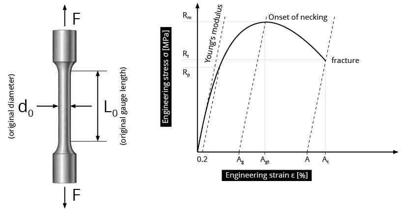
Engineering stress is calculated from the applied force and the initial cross-sectional area A0 of the specimen. The cross-sectional geometry must therefore be characterized adequately to determine A0.
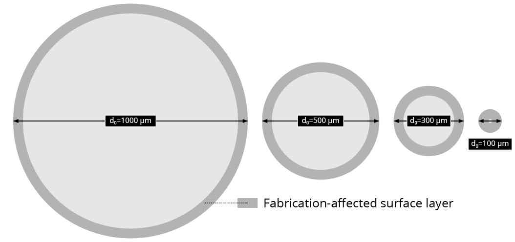
At the microscale, this makes the difference between an idealized geometry and the real specimen geometry particularly relevant.
Ideal Cross Sections Are Mathematically Simple
For an ideal rectangular cross section with width b and thickness t, the area is
A = bt
For an ideal circular cross section with diameter d, the area is
A = \frac{\pi d^{2}}{4}
Both geometries are mathematically simple. The advantage of a round cross section therefore does not result simply from comparing these two equations.
The relevant question is whether the real cross section is adequately represented by the assumed geometrical model. For an ideal rectangle, width and thickness are sufficient. If the real geometry deviates from this ideal, additional geometrical information may be required.
Real Micro Cross Sections Require an Appropriate Geometrical Description
A nominally rectangular micro specimen does not necessarily have an ideal rectangular cross section. Deviations from orthogonality, rounded edges, burrs, edge breakouts, notches or other local contour deviations can change the actual cross-sectional geometry.
The resulting progression can be considered step by step:
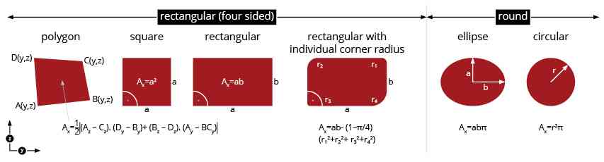
ideal rectangle → rectangle with rounded edges → general four-sided polygon → four-sided geometry with rounded edges or additional contour features
For the ideal rectangle, the area is described by two dimensions:
A = bt
Adding defined edge radii requires additional geometrical information to describe the rounded regions. If the four sides no longer form a rectangle, the actual geometry can, where appropriate, be represented as a general four-sided polygon. Its area remains mathematically determinable, but the geometrical information defining that polygon is required.
If such a four-sided geometry additionally contains rounded edges or other relevant local contour features, these features must also be represented adequately if they affect the required area determination.
The progression is therefore not from a calculable to an incalculable cross section. Instead, increasing deviation from the idealized geometry can require additional geometrical quantities or a more detailed description of the actual contour.
The corresponding area relationships are shown with the individual geometries so that the increasing amount of geometrical information required for area determination becomes directly visible.
Precise Measurements Require an Appropriate Geometrical Model
The accuracy of individual dimensional measurements and the adequacy of the underlying geometrical model are separate questions.
If
A = bt
is used, width b and thickness t must adequately describe the relevant real cross section. If relevant geometrical features are not represented in this area model, they are not accounted for simply by measuring b and t more precisely.
A precise measurement does not compensate for an incomplete geometrical model.
The same distinction applies to uncertainty analysis: evaluating the measurement uncertainties of the quantities included in a model does not automatically account for relevant geometrical features that are absent from that model.
The detailed treatment of dimensional measurement and measurement uncertainty is addressed in Diameter Measurement and Stress Calculation in Micro Tensile Testing.
Why a Round Cross Section Reduces Geometrical Complexity
For a sufficiently circular cross section, the area is determined from
A = \frac{\pi d^{2}}{4}
The practical advantage is not that other cross-sectional geometries cannot be calculated. Their area can be determined if the relevant actual geometry is sufficiently characterized.
The advantage of the circular cross section is that the geometrical description required for area determination can be reduced to the specimen diameter as the central geometrical quantity. Additional parameters for angles, individual sides or local contour features are not required as long as the real cross section is adequately represented by the circular model.
However, reducing the geometrical description to one parameter does not mean that a single measurement is sufficient:
One geometrical parameter does not mean one measurement.
The diameter must be characterized in a way that also allows the assumed circular geometry to be checked.
How the Circular Geometry Is Verified
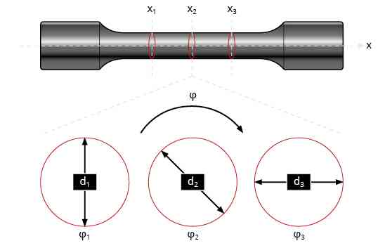
In the current microsample measurement concept, the initial specimen diameter d0 is determined from diameter measurements at several positions along the tensile axis and at different rotation angles. Measurements at different rotation angles also support the assessment of circularity.
These measurements provide different geometrical information. Measurements at different rotation angles can reveal deviations from the assumed circular shape, while measurements at several axial positions characterize the diameter along the relevant tensile section.
They do not demonstrate a mathematically perfect circle. Rather, they provide a means of checking whether the real specimen geometry is adequately represented by the circular model used for area determination.
An elliptical cross section illustrates the limit of this assumption. For an ellipse with principal diameters D1 and D2,
A = \frac{\pi D_{1} D_{2}}{4}
Using the arithmetic mean of D1 and D2 as the diameter in the circular-area equation does not generally produce the same area. Different diameter measurements therefore cannot simply be averaged to convert a non-circular cross section into an equivalent circular one.
The intended rotationally symmetric tensile geometry must therefore be produced in a controlled preparation process and the resulting real geometry subsequently verified. The preparation principle is described in How Are Round Micro Tensile Specimens Manufactured?
From Cross-Sectional Geometry to Stress Calculation
Once the real cross section has been adequately represented and the circular geometry verified, the initial cross-sectional area can be determined from
A_{0} = \frac{\pi d_{0}^{2}}{4}
The geometrical question addressed in this article therefore ends with establishing the basis for A0.
How d0 is determined, how its measurement uncertainty affects A0, and how cross-sectional area and force measurement influence engineering stress are addressed in Diameter Measurement and Stress Calculation in Micro Tensile Testing.