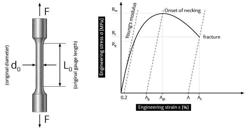
During a tensile test, not only the length of the specimen changes. Its cross-sectional area changes as well. This change becomes particularly important once necking begins and the reduction in cross section becomes increasingly localized.
The changing cross section is therefore an important measured quantity in tensile testing. It is required to describe the actual load-bearing area of the specimen and, at the end of the test, provides the basis for determining reduction of area.
For round micro tensile specimens, the local cross section can be determined particularly directly from the specimen diameter, provided that the cross section remains sufficiently circular. This makes it possible to follow the development of the minimum cross section as necking progresses.
Why the Changing Cross Section Matters
Engineering stress relates the applied force to the initial cross-sectional area:
\sigma_{\mathrm{eng}} = \frac{F}{A_{0}}
The initial area A0 remains the reference throughout the test, even though the specimen becomes thinner during tensile deformation.
True stress takes this change into account by relating the current force to the current minimum cross-sectional area:
\sigma_{\mathrm{true}}(t) = \frac{F(t)}{A_{\min}(t)}
The current cross-sectional area is therefore relevant independently of the original specimen dimensions. As the specimen begins to neck, the minimum cross section becomes progressively smaller and increasingly characterizes the local geometrical development of the specimen.
True stress and reduction of area use this information for different purposes. True stress relates force to the current cross section. Reduction of area describes how much the cross section itself has decreased.
The detailed relationship between diameter, area and stress is discussed in Diameter Measurement and Stress Calculation in Micro Tensile Testing.
From Current Cross Section to Reduction of Area
Reduction of area describes the relative decrease from the initial cross-sectional area A0 to the final minimum cross-sectional area Af:
Z = \frac{A_{0} – A_{f}}{A_{0}} \times 100\,\%
where:
- Z = reduction of area
- A0 = initial cross-sectional area
- Af = final minimum cross-sectional area
For an initially circular specimen,
A_{0} = \frac{\pi d_{0}^{2}}{4}
and, if the final minimum cross section can also be adequately described as circular,
A_{f} = \frac{\pi d_{f}^{2}}{4}
This gives:
Z = \left[1 – \left(\frac{d_{f}}{d_{0}}\right)^{2}\right] \times 100\,\%
Reduction of area is therefore based on the change in cross-sectional area. No change in length or gauge length enters into the calculation of Z.
From Uniform Deformation to Necking
Once necking begins, the reduction in cross section becomes increasingly localized. The minimum diameter decreases and the local load-bearing area becomes smaller as deformation progresses toward fracture.
Reduction of area characterizes the extent of this local cross-sectional contraction.
Why Round Specimens Make the Cross Section Accessible
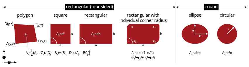
For an ideal round cross section,
A = \frac{\pi d^{2}}{4}
The cross-sectional area can therefore be determined from one central geometrical quantity: the diameter. This is particularly useful for following necking, because changes in the local diameter can be converted directly into changes in cross-sectional area.
This relationship requires the local cross section to be adequately represented as circular. If the neck becomes distinctly elliptical or otherwise non-axisymmetric, a single measured width no longer completely defines the actual cross-sectional area.
A round, rotationally symmetric specimen therefore provides a direct geometrical relationship between measured diameter and calculated area. The geometrical significance of round specimens is discussed in more detail in Why Round Specimens Matter in Micro Tensile Testing.
Tracking Necking During the Tensile Test
Optical observation of the specimen contour makes it possible to determine the minimum specimen diameter during the tensile test and to follow its development as deformation progresses.
For a sufficiently circular cross section, this provides a direct relationship:
d_{\min}(t) \rightarrow A_{\min}(t)
The development of the minimum cross section can therefore be followed throughout necking rather than being characterized only by measurements of the initial and final specimen geometry.
Rathmayr et al. (2013) demonstrated this principle using image sequences recorded during tensile testing of sub-millimetre specimens. In the published method, the specimen contour was evaluated during the test, allowing the development of the local cross section to be followed as deformation progressed.
The published HPT-deformed nickel experiment shows engineering stress, true stress and reduction of area during the tensile test. It provides an experimental example of how the reduction of the minimum cross-sectional area can be followed together with the mechanical test data.
(Reprinted, with permission, from the Journal of Testing and Evaluation, Vol. 41, Issue 4, copyright ASTM International, 100 Barr Harbor Drive, West Conshohocken, PA 19428.)
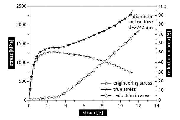
(Reprinted, with permission, from the Journal of Testing and Evaluation, Vol. 41, Issue 4, copyright ASTM International, 100 Barr Harbor Drive, West Conshohocken, PA 19428.)
Reduction of Area and Elongation Describe Different Information
Elongation and reduction of area are both used to characterize tensile ductility, but they are based on different geometrical changes.
Elongation is based on a change in length over a defined gauge length. Reduction of area, in contrast, is based on the change in cross-sectional area.
Reduction of area is therefore not a strain calculation. It provides information about the local cross-sectional contraction associated with necking that is not provided by a length-based elongation value alone.
Strain and its measurement in micro tensile testing are discussed separately in Strain and Displacement Measurement in Micro Tensile Testing.
Experimental Check of the Final Neck Geometry
Optical monitoring can follow the specimen geometry until immediately before fracture, when the neck is strongly developed.
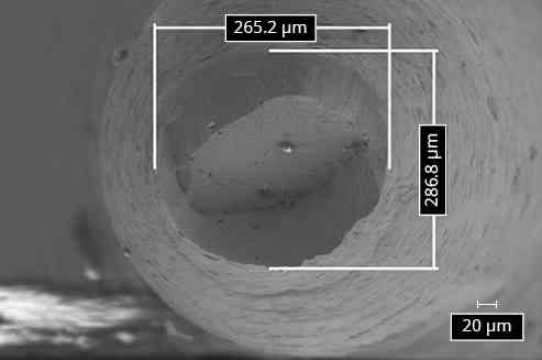
In the HPT-deformed nickel experiment reported by Rathmayr et al. (2013), the final neck geometry was evaluated in two ways. The SEM image of the fracture surface shows two measured dimensions of the fracture cross section. Their similar values support the assumption of an approximately circular fracture cross section for the investigated specimen, which is required to determine the cross-sectional area from a single diameter using A = πd2/4.
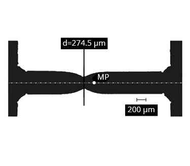
The last optical image before fracture shows the numerically evaluated specimen contour. The evaluation identifies the position of the minimum cross section and the corresponding minimum diameter df used for the reduction-of-area evaluation.
For the investigated specimen, the optically determined final neck geometry and the subsequently measured fracture geometry showed good agreement. This provides an experimental check of the optical contour-based evaluation for this specimen and published test setup. It does not establish a general accuracy specification or demonstrate that the fracture cross section remains circular for other materials or specimen geometries.
(Reprinted, with permission, from the Journal of Testing and Evaluation, Vol. 41, Issue 4, copyright ASTM International, 100 Barr Harbor Drive, West Conshohocken, PA 19428.)
 (Reprinted, with permission, from the Journal of Testing and Evaluation, Vol. 41, Issue 4, copyright ASTM International, 100 Barr Harbor Drive, West Conshohocken, PA 19428.) |
 |
What Does Reduction of Area Tell Us?
Reduction of area characterizes the local cross-sectional contraction associated with necking and fracture.
A larger reduction of area corresponds to a greater decrease in the local cross section before separation, while a smaller value corresponds to less local cross-sectional contraction.
It therefore complements elongation by providing information about a different geometrical aspect of tensile ductility: the local contraction of the specimen rather than its change in length.
Conclusion
Reduction of area describes the local decrease in cross-sectional area associated with necking and fracture. For round micro tensile specimens, the direct relationship between diameter and area makes this change accessible through diameter measurement, provided that the local cross section can be adequately represented as circular.
Optical monitoring can extend this evaluation from the initial and final cross sections to the development of the minimum cross section during the tensile test, providing direct information about the progression of local cross-sectional reduction.
Related Knowledge Base Articles
- What Is Micro Tensile Testing?
- How Are Round Micro Tensile Specimens Manufactured?
- Why Round Specimens Matter in Micro Tensile Testing
- Diameter Measurement and Stress Calculation in Micro Tensile Testing
- Strain and Displacement Measurement in Micro Tensile Testing
Scientific Reference
Rathmayr, G. B., Bachmaier, A., and Pippan, R., “Development of a New Testing Procedure for Performing Tensile Tests on Specimens with Sub-Millimetre Dimensions,” Journal of Testing and Evaluation, Vol. 41, No. 4, 2013, pp. 635–646. DOI: 10.1520/JTE20120175.