BACKGROUND
What is importantTENSILE TESTING IN SMALL DIMENSIONS
Conventional uniaxial tensile testing is one of the well-established test procedures to determine a large number of mechanical properties of engineering materials. The most important parameters influencing data quality during testing of small scaled specimens are summarized in the following. Further details can be found here.
SPECIMEN GEOMETRY
For specimen dimensions below 1 mm, it makes a difference if specimens with a round or rectangular cross-section are tested.
One of the reasons is that it is almost impossible to fabricate specimens with a rectangular cross-section having precisely an enclosed angle between the two lateral faces of 90° with common specimen fabrication methods like electrical discharge machining and mechanical milling. Furthermore, the edges of the rectangular specimen will always be rather round. If the shape of the specimen is not perfectly rectangular, the formula of a four-sided polygon would have to be used to calculate the real cross sectional area of the specimen.
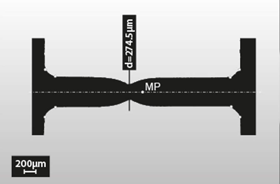
Additionally, the accurate measurement of the dimensions of the specimen is a challenge. Specimens made with our tool have a round cross-section and the rotational symmetry improves the accuracy of the specimen dimension measurement.
The final specimen dimensions are measured with high precision using a 2D optical micrometer system. This measurement can also be performed between the individual fabrication steps to control the actual specimen geometry in order to achieve the highest accuracy.
SPECIMEN FABRICATION
Maximized precision of the specimen preparation is an important requirement for specimens with a cross-section diameter less than 1 mm. This includes a high accuracy of the specimen dimensions avoiding burrs or notches and a perfect surface, without grooves and high roughness, is an additional essential need. Any change in the “tested material” due to the fabrication method, like cold working or overheating, must be avoided.
A low influence on the material during shaping is caused by the grinding process. No heat affected zone leading to micro cracks or residual stresses and no local melting of the specimen surface like in electrical discharge machining occurs. Additionally, the surface is not influenced by cutting stresses, striations and the machining heat like during milling.
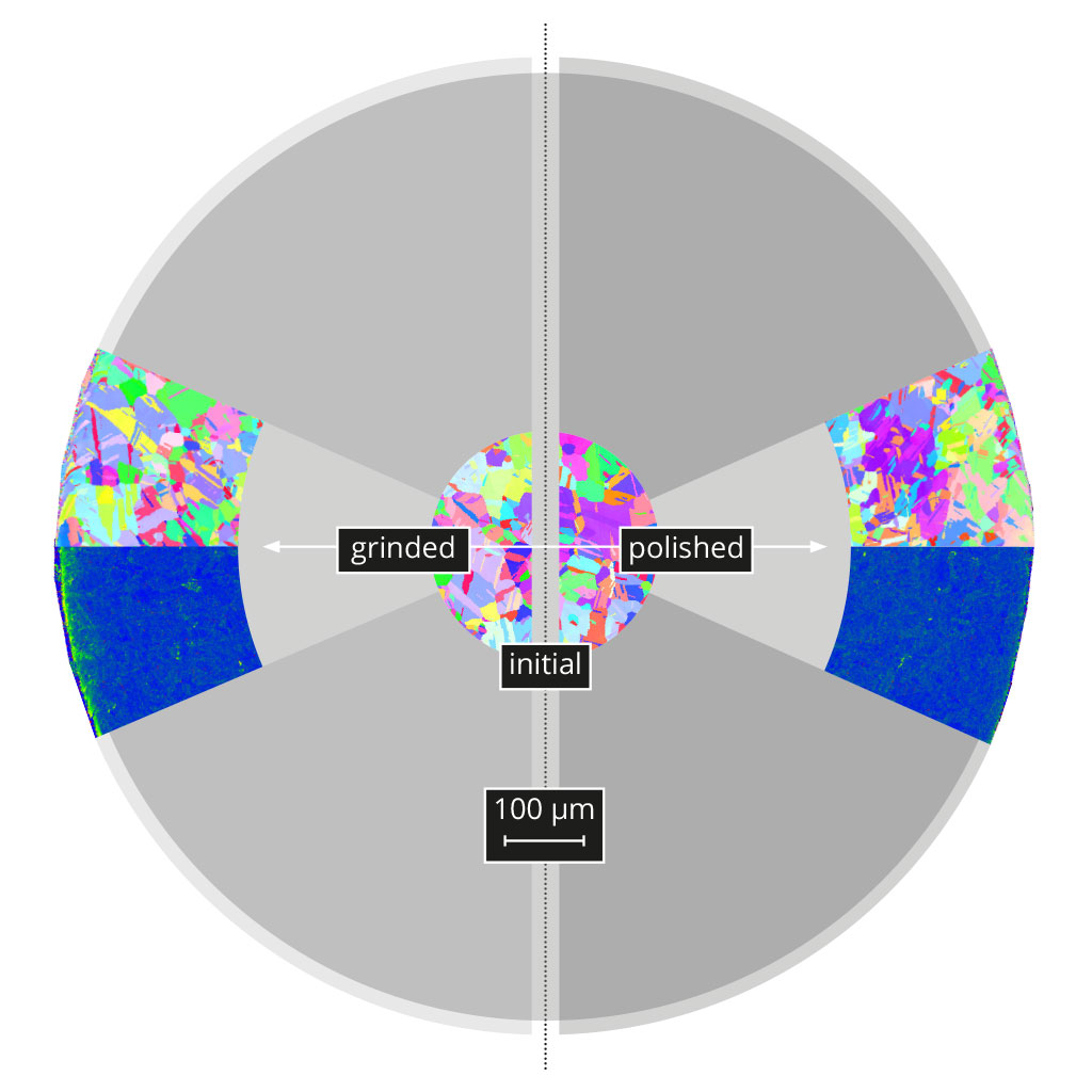
The low influence of the fabrication process on the material itself and the high quality of the specimen surface can be seen in the examples above. No difference between the microstructure in the initial and as-fabricated condition of a tensile test specimen fabricated from commercially available copper (annealed for 1h at 500°C in vacuum before specimen fabrication) can be observed in the Electron Back Scatter Diffraction images.
Initial material (centre) and material after applying the grinding and polishing process (left hand): No difference in the microstructure is visible.
The positive influence of a subsequent polishing step is shown in the Kernel average misorientation maps. On the left side, the material after grinding is visible which exhibits a small mechanically deteriorated layer due to the grinding process. After final polishing, this layer is removed and specimen surfaces finishes with high quality are obtained (image on right side).
REPRODUCIBILITY
The Gaussian error calculation shows that the correct determination of the cross-section area has the hugest influence on stress calculation if small scaled specimens are used. Decreasing cross-section areas intensify this effect still further.
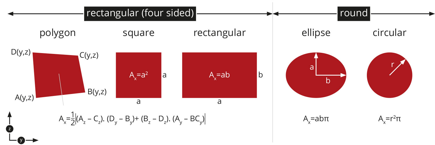
Basic requirement for an error calculation is a precise mathematical description of the cross-section area as a function of a measured variable. In case of a round cross-section this is the diameter, in case of a rectangular cross section it is the length of the rectangle. Besides the difficulty with the measurement itself, the orthogonality of a four-sided cross-section must be always proved. Only then the simplified/classical formula for the calculation of the cross-section of a rectangle can be used. Otherwise, the formula of a four-sided polygon as given in the figure below has to be used to calculate the real cross-sectional area of the specimen. The latter needs as a measured variable the xy-coordinates of each vertex. The final hurdle is the experimental verification that the edges of the specimen are perfectly sharp (not rounded) and contain no cracks or notches.
If specimens with a rectangular cross section with dimensions below 1 mm are used, the edges will always be rather round than perfectly sharp and the experimental verification of orthogonality in finite time is simply not possible. To reliably and reproducibly conduct a tensile test on the meso-scale, the use of a round cross-section is therefore highly recommended.
Different cross sections
In the following, the influence of incorrect determination of the specimen dimensions is shown:
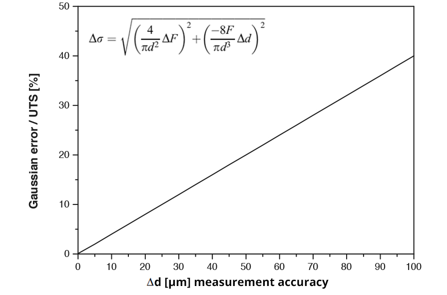
By simply dividing the tensile force (F) by the cross-sectional area of the specimen (A), the stress σ can be calculated. The measurement error can be determined with a Gaussian error calculation as given in the figure below. In the formula given, Δσ (MPa) denotes the accuracy error, F the tension force, ΔF is the accuracy of the load cell, and Δd the accuracy of the diameter measurement of the specimen.
To give a numerical example: A specimen with a cross section diameter of 500 µm is tested using a load cell of 2000 N. The force inaccuracy of the load cell is 1‰ (ΔF=2mN), which causes a negligible contribution to the total error to the flow stress. An error of 10% of the ultimate tensile stress has to be taken into account by keeping an accuracy of Δd=25 µm; for accuracy of Δd=5 µm, the error is reduced to about 2%.
DISPLACEMENT MEASURMENT
Measuring accurate displacements while performing a test at this size scale can be difficult due to the following reasons:
A clip gauge, which would be a highly accurate displacement measurement system, cannot easily be applied to small specimens. The region sampled by a laser speckle extensometer is too large for the application to specimens with small dimension. If simply the cross-head movement is used, there is a strong influence of the machine compliance.
However, an incorrect determination of the displacement during tensile testing leads to significant different results!
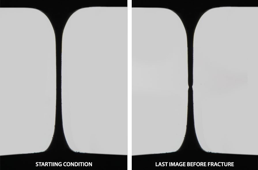
We developed a new experimental test setup to overcome the above mentioned problems. During testing, the actual specimen geometry is continuously monitored using a recording camera which is remote-controlled. Hence, easy correlation between the recorded frames and tensile stage data is possible. Every single frame delivers the current specimen diameter and all diameters over the gauge are provided. The transmitted light used in our test set up provides constant lighting conditions during the whole experiment, focus adjustment is not required, and a sharp contrast between specimen and background is guaranteed. A numerical evaluation software gives the opportunity to analyse tensile test data with high efficiency after the experiment.
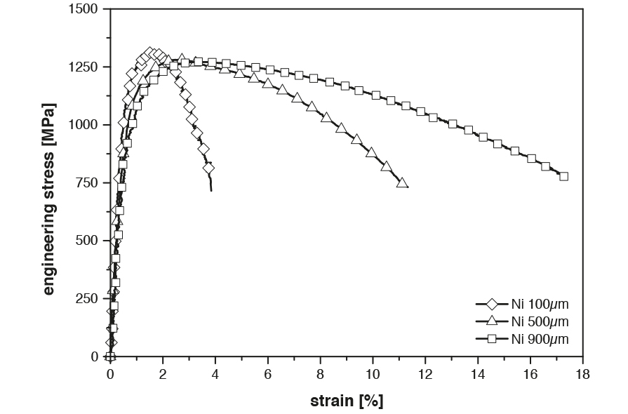
Typical application examples:
A quick quality check of a tensile test is to calculate the Young’s modulus from the recorded test data and compare it to the given Young’s modulus of the tested material. For different tested Ni specimens, a mean Young’s modulus of 216±31.2 GPa is determined using our test setup, which is in good agreement with the literature value of 200 GPa.
A quick quality check of a tensile test is to calculate the Young’s modulus from the recorded test data and compare it to the given Young’s modulus of the tested material. For different tested Ni specimens, a mean Young’s modulus of 216±31.2 GPa is determined using our test setup, which is in good agreement with the literature value of 200 GPa.
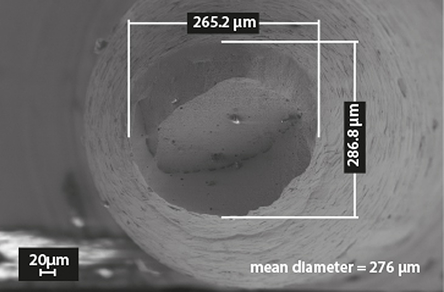
The figure below shows the actual radius measured from the fracture surface by scanning electron microscopy compared to the reduction in area in the event of fracture, which is determined by the software. An relative error of less than 1% is determined.
SPECIMEN LOADING
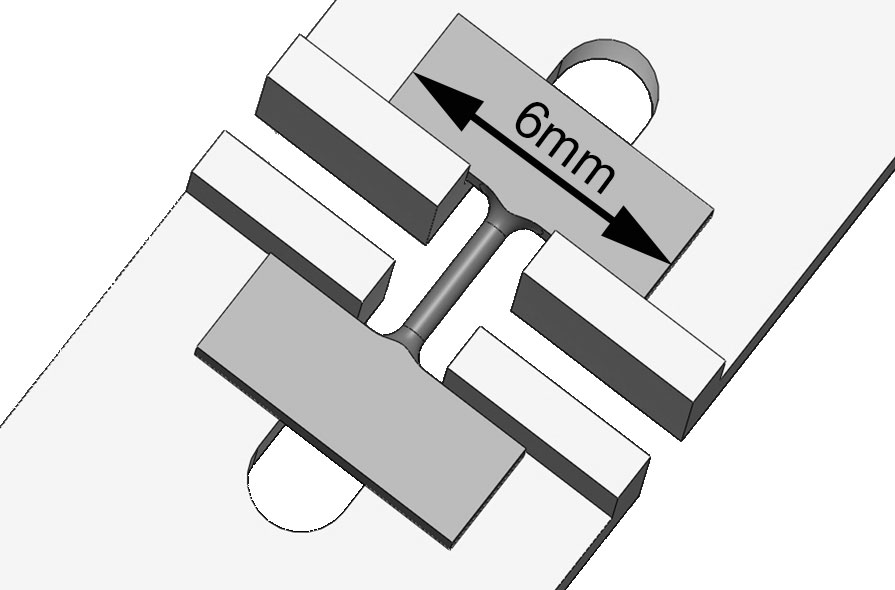
All available specimen displacement measuring systems are very sensitive to the bending of the specimen. In our case, the specimen is rotationally symmetric, which prevents the occurrence of a bending moment during testing.
REFERENCES
The specimen fabrication and test method was developed in cooperation with the Erich Schmid Institute, Austrian Academy of Science, Austria (http://esi.oeaw.ac.at/).
The specimen fabrication and test method has already been used in research:
L. Krämer, S. Wurster, R. Pippan, IOP Conference Series:
Materials Science and Engineering, Volume 63, conference 1, 2014, 012026
G.B. Rathmayr, A. Hohenwarter, R. Pippan, Materials Science and Engineering:
A, Vol. 560, 2013, Pages 224–231
G.B. Rathmayr, A. Bachmaier, R. Pippan, Journal of Testing and Evaluation:
Vol. 41, No. 4, 2013, Pages 1-12
GET IN TOUCH

Der Aufbau des Dienstleistungsbereichs wird vom Bundesministerium für Wissenschaft, Forschung und Wirtschaft und der Europäischen Union unterstüzt.