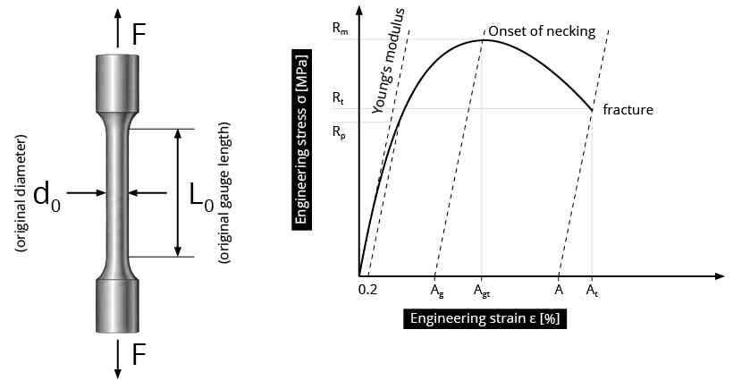
Measuring tensile force on a small specimen and measuring its deformation are two different tasks. Force can be measured directly by the load cell. Strain, however, is derived from a change in length of a defined part of the specimen.
In conventional tensile testing, deformation can often be measured using an extensometer attached directly to the gauge section. For micro tensile specimens with gauge lengths of only a few millimetres or less, this becomes considerably more difficult. The deformation to be measured is small, the available attachment area is limited, and the measurement system itself must not significantly disturb the specimen.
A central question in micro tensile testing is therefore not only how precisely displacement is measured, but which displacement is measured and what part of the actual specimen deformation it represents.
Crosshead displacement, fixture displacement and specimen displacement are not necessarily identical.
Displacement Is Not the Same as Strain
Displacement describes an absolute change in distance. If an initial gauge length L0 changes by ΔL, the engineering strain is
\varepsilon_{\mathrm{eng}} = \frac{\Delta L}{L_{0}}
The equation itself is simple. The important question is what displacement ΔL represents and which initial length L0 is used as its reference.
If displacement is measured outside the relevant specimen region, the measured movement can contain contributions that do not originate from deformation of the material volume being evaluated. For this reason, the origin of the measured displacement is just as important as its numerical resolution.
Why Crosshead Displacement Can Be Misleading
A tensile-testing machine applies displacement through its loading system. It is therefore tempting to use crosshead movement directly as a measure of specimen elongation.
Conceptually, however, the measured crosshead displacement can contain several contributions:
\Delta L_{\mathrm{crosshead}} = \Delta L_{\mathrm{specimen}} + \Delta L_{\mathrm{machine}} + \Delta L_{\mathrm{fixture}} + \Delta L_{\mathrm{contacts}}
This is a conceptual decomposition rather than an uncertainty equation. It illustrates why crosshead movement is not automatically equal to specimen elongation.
Elastic deformation of the test frame and loading system is generally referred to as machine compliance. Additional displacement can arise from fixtures and from contacts between the specimen and loading components. Rathmayr et al. (2013) identified machine compliance and contact between the specimen shoulders and the loading device as relevant limitations when crosshead movement is used for displacement measurement in miniaturized tensile tests.
The effect becomes increasingly important when the displacement of the specimen itself is small. A system-related displacement that represents only a minor contribution for a specimen with a comparatively long measurement length can represent a much larger fraction of the measured movement for a micro tensile specimen.
Reducing specimen dimensions therefore does not simply reduce all displacement contributions proportionally. Some originate from the testing system rather than from the specimen. The shorter the measurement length, the more carefully the origin of the measured displacement must be considered.
Experimental Evidence of Machine Compliance
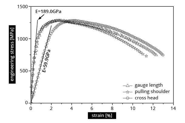
Rathmayr et al. (2013) provide a particularly clear experimental illustration. A tensile test on an HPT-deformed nickel specimen was evaluated using three displacement approaches: crosshead movement, displacement derived from the pulling shoulders, and displacement derived from the gauge length.
For this specimen and test setup, the stress–strain curve calculated from crosshead displacement produced an apparent Young’s modulus of only about one third of the literature value of approximately 200 GPa. The curves obtained from the two specimen-related optical displacement methods were nearly identical up to uniform elongation and produced a modulus much closer to the literature value.
The experiment demonstrates why crosshead displacement cannot automatically be treated as specimen elongation. The magnitude of the effect depends on the test system, fixtures, specimen and measurement arrangement; the published result therefore does not provide a universal correction factor.
Why Specimen-Based Optical Measurement Is Useful
An extensometer attached directly to a specimen is intended to measure deformation without relying solely on movement of the test machine. At very small specimen dimensions, however, mechanical attachment becomes increasingly difficult.
Rathmayr et al. (2013) discuss this problem for sub-millimetre specimens and short gauge lengths. In addition to the limited attachment area, a measurement device applied to a very small specimen must introduce sufficiently little force and moment that it does not itself significantly affect specimen alignment or deformation.
Contact-free optical measurement provides another approach. Instead of deriving deformation solely from test-machine movement, geometrical positions or contours of the specimen can be observed during the tensile test.
Deformation can be measured relative to the specimen itself rather than inferred solely from test-machine movement.
Image-Based Specimen Displacement Measurement
The image-based method described by Rathmayr et al. (2013) records the specimen during the tensile test and derives displacement from geometrical reference positions associated with the specimen. In the published implementation, this allowed specimen-related displacement to be determined without additional printed strain markers.
For contour-based measurement, the specimen boundary must be clearly identifiable. Transmitted-light imaging was used in the published method to provide a distinct contrast between specimen and background and thereby support geometrical evaluation of the specimen contour.
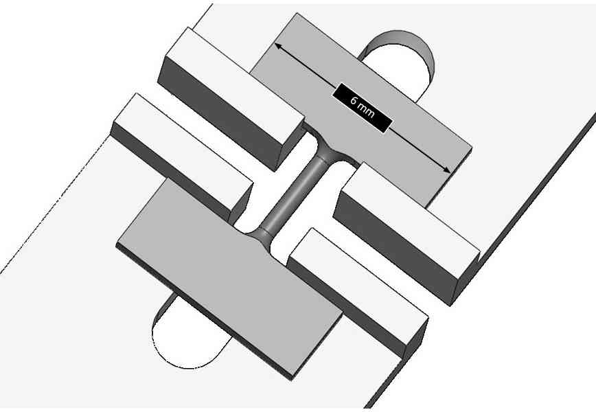
The wider pulling shoulders provide the interface for introducing the tensile load into the small cylindrical tensile section. The transition from the pulling shoulders to the gauge section is formed by fillet regions. In the published setup, the pulling shoulders also provided specimen-related geometrical references for displacement measurement.
The measured displacement also depends on where deformation is referenced on the specimen. Different reference positions can include different parts of the specimen deformation. This is why specimen-based measurement must be associated with a defined geometrical reference rather than being understood simply as “optical displacement”.
The underlying principle is broader than the particular optical implementation: directly observing the specimen makes it possible to derive deformation from specimen-related geometrical information rather than exclusively from movement of the testing system.
Engineering Strain, True Strain and Local Deformation
Engineering strain relates a change in length to the initial reference length:
\varepsilon_{\mathrm{eng}} = \frac{\Delta L}{L_{0}}
For homogeneous uniaxial elongation, logarithmic true strain can be expressed as
\varepsilon_{\mathrm{true}} = \ln\left(\frac{L}{L_{0}}\right)
and, for the same length-based description,
\varepsilon_{\mathrm{true}} = \ln(1 + \varepsilon_{\mathrm{eng}})
Once necking begins, however, deformation becomes increasingly localized. A strain value derived from a change in length over a defined gauge length then does not directly describe the local deformation within the neck. Global strain and local deformation should therefore not be used interchangeably.
The evolution of the local cross section and the determination of reduction of area are discussed separately in KB07 – Reduction of Area in Micro Tensile Testing.
Young’s Modulus as a Validity Check
The elastic part of the stress–strain curve provides an important check on the validity of displacement and strain measurement.
If measured strain contains substantial deformation of the test machine, fixtures or contacts, the apparent slope of the elastic region can become too low. The HPT-nickel experiment discussed above demonstrates this directly: evaluation based on crosshead displacement produced a substantially lower apparent Young’s modulus than the specimen-related optical evaluations.
Comparison with an appropriate Young’s modulus can therefore help identify problems in displacement or strain determination.
However, agreement with a reference value alone does not validate every aspect of a tensile test. The expected modulus must itself be appropriate for the investigated material and condition. Material state, texture, anisotropy, microstructure and other relevant conditions may need to be considered when interpreting deviations.
Optical measurement likewise does not become accurate simply because it is contact-free or camera-based. The complete measurement chain must provide a suitable and validated displacement measurement, and appropriate specimen alignment and axial load introduction remain necessary.
The objective is not simply to measure movement with the smallest possible numerical resolution, but to measure the displacement that actually represents the deformation of the material volume being evaluated.
Related Knowledge Base Articles
- What Is Micro Tensile Testing?
- Why Round Specimens Matter in Micro Tensile Testing
- Diameter Measurement and Stress Calculation in Micro Tensile Testing
- Reduction of Area in Micro Tensile Testing
Scientific Reference
Rathmayr, G. B., Bachmaier, A., and Pippan, R., “Development of a New Testing Procedure for Performing Tensile Tests on Specimens with Sub-Millimetre Dimensions,” Journal of Testing and Evaluation, Vol. 41, No. 4, 2013, pp. 635–646. DOI: 10.1520/JTE20120175.