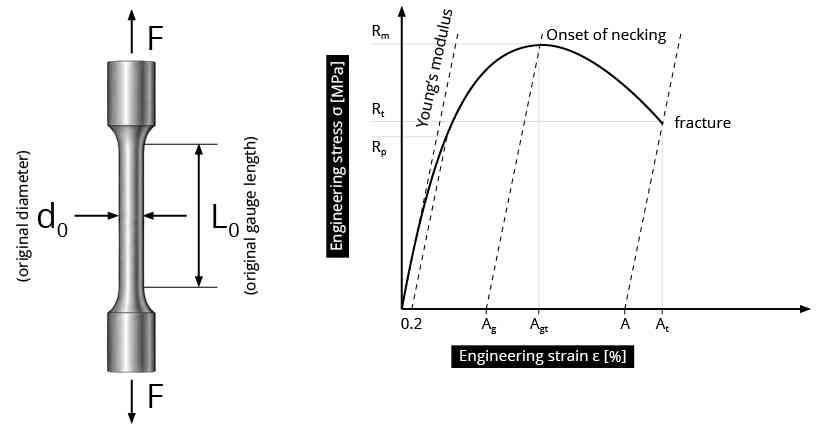
Tensile stress is calculated from two measured quantities: the applied tensile force and the load-bearing cross-sectional area of the specimen.
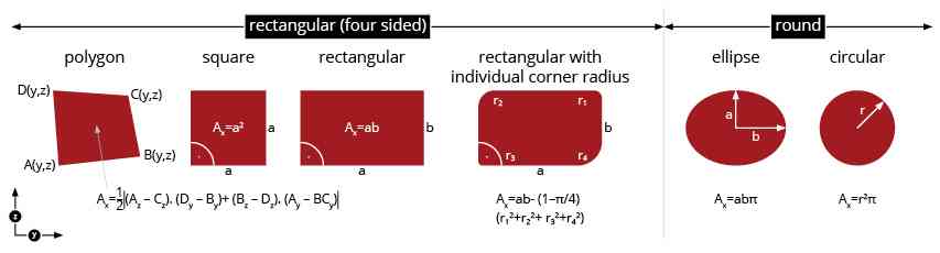
For a round micro tensile specimen, the cross-sectional area is determined from its diameter. This makes diameter measurement a direct part of the stress calculation rather than merely a geometrical quality check.
As specimen dimensions decrease, a given absolute dimensional measurement error represents an increasingly large fraction of the specimen dimension. The resulting influence on the calculated cross-sectional area — and therefore on calculated stress — can consequently become significant.
For micro tensile testing, force measurement and dimensional measurement must therefore be considered together.
From Tensile Force to Stress
Engineering stress is calculated as
\sigma_{\mathrm{eng}} = \frac{F}{A_0}
where F is the tensile force and A0 is the initial cross-sectional area.
For an ideally circular cross section,
A_0 = \frac{\pi d_0^2}{4}
and therefore
\sigma_{\mathrm{eng}} = \frac{4F}{\pi d_0^2}
where d0 is the initial specimen diameter.
The measured diameter enters the calculation of the cross-sectional area as a squared quantity. The use of this equation requires that the circular cross-section model is an adequate representation of the actual specimen geometry. The geometrical requirements and verification of a round cross section are discussed separately in Why Round Specimens Matter in Micro Tensile Testing.
Gaussian Error Propagation
The influence of force and diameter measurement errors on the calculated engineering stress can be described using Gaussian error propagation. For
\sigma_{\mathrm{eng}} = \sigma_{\mathrm{eng}}(F, d_0)
and independent errors ΔF and Δd0, the propagated error is
\Delta\sigma_{\mathrm{eng}} = \sqrt{\left(\frac{\partial\sigma_{\mathrm{eng}}}{\partial F}\cdot\Delta F\right)^2 + \left(\frac{\partial\sigma_{\mathrm{eng}}}{\partial d_0}\cdot\Delta d_0\right)^2}
For
\sigma_{\mathrm{eng}} = \frac{4F}{\pi d_0^2}
the partial derivatives are
\frac{\partial\sigma_{\mathrm{eng}}}{\partial F} = \frac{4}{\pi d_0^2}
and
\frac{\partial\sigma_{\mathrm{eng}}}{\partial d_0} = -\frac{8F}{\pi d_0^3}
This gives
\Delta\sigma_{\mathrm{eng}} = \sqrt{\left(\frac{4}{\pi d_0^2}\cdot\Delta F\right)^2 + \left(\frac{8F}{\pi d_0^3}\cdot\Delta d_0\right)^2}
The sign of the diameter derivative is irrelevant because the contribution is squared.
Expressed in relative terms,
\frac{\Delta\sigma_{\mathrm{eng}}}{\sigma_{\mathrm{eng}}} = \sqrt{\left(\frac{\Delta F}{F}\right)^2 + \left(2\frac{\Delta d_0}{d_0}\right)^2}
This relationship separates the contributions of force and diameter measurement and provides the basis for assessing their influence on the calculated engineering stress.
The value of Δd0 cannot be derived from the nominal resolution of the diameter measurement system alone.
Interpreting the Influence of Force and Diameter Measurement
For the circular cross-section model, the relative force measurement error enters the propagated error with a factor of one, whereas the relative diameter measurement error enters with a factor of two:
\frac{\Delta\sigma_{\mathrm{eng}}}{\sigma_{\mathrm{eng}}} = \sqrt{\left(1\cdot\frac{\Delta F}{F}\right)^2 + \left(2\cdot\frac{\Delta d_0}{d_0}\right)^2}
A given relative error in diameter therefore has approximately twice the relative contribution to the calculated stress compared with the same relative error in force.
This does not mean that diameter measurement generally dominates the uncertainty of a micro tensile test. The actual contributions depend on the respective values of ΔF/F and Δd0/d0.
If only the contribution resulting from the diameter measurement error is considered,
\left(\frac{\Delta\sigma_{\mathrm{eng}}}{\sigma_{\mathrm{eng}}}\right)_{d} = 2\cdot\frac{\Delta d_0}{d_0}
The subscript d indicates that this expression represents only the contribution resulting from the diameter measurement error Δd0. The contribution of the force measurement error ΔF is not included. For a constant absolute diameter measurement error, this relative contribution therefore increases as the specimen diameter decreases.
For example, an absolute diameter measurement error of 5 µm corresponds to a diameter-related contribution to the calculated engineering stress of approximately:
- 1 % at d0 = 1000 µm
- 2 % at d0 = 500 µm
- 4 % at d0 = 250 µm
- 10 % at d0 = 100 µm
These values are mathematical illustrations of the relationship above. They are not specifications for the accuracy or measurement uncertainty of the current microsample measurement system.
This scaling is not specific to round specimens: the relative influence of a constant absolute dimensional measurement error generally increases as the relevant specimen dimensions decrease. The specific error propagation, however, depends on the geometrical quantities used to determine the cross-sectional area.
Published Example for a 0.5 mm Specimen
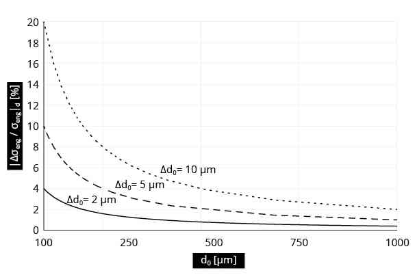
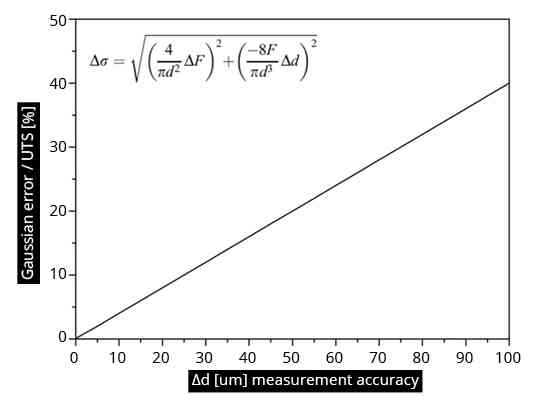
The 2013 JTE publication by Rathmayr, Bachmaier and Pippan provides a numerical example of the complete Gaussian error propagation, including both force and diameter measurement errors, for a specimen with a nominal diameter of 0.5 mm.
In the published calculation, the force inaccuracy was taken as 0.2 N, corresponding to 0.1 % of the maximum load capacity of the load cell used in that study. For the investigated high-strength SPD material, the contribution of the force measurement error was small compared with the contribution from diameter measurement.
For a diameter measurement error of Δd = 25 µm, the publication reports a calculated error of approximately 10 % of the ultimate tensile strength. Reducing Δd to 5 µm reduces the calculated error to approximately 2 %.
These values describe the specific calculation presented in the publication. They are not specifications for current microsample measurement equipment or generally applicable error values for micro tensile testing.
As an example of how to read the graph, a diameter measurement error of Δd = 5 µm corresponds to a calculated Gaussian error of approximately 2 % of the ultimate tensile strength for the 0.5 mm specimen considered in the publication. At Δd = 25 µm, the corresponding value increases to approximately 10 %.
Measuring the Initial Diameter d0
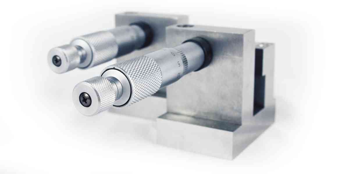
In the current microsample measurement concept, the initial diameter d0 is determined on each finished specimen before the tensile test using a 2D transmitted-light micrometer.
Diameter measurements are performed at several positions along the tensile axis and at different rotation angles. From these measurements, the mean initial diameter d0 is determined.
Measurements at different rotation angles also support verification of the circular cross section. The geometrical significance and limitations of this verification are discussed in Why Round Specimens Matter in Micro Tensile Testing.
For a sufficiently circular cross section, the measured initial diameter is used to determine
A_0 = \frac{\pi d_0^2}{4}
which provides the reference area for calculating engineering stress.
The initial diameter d0 and initial area A0 remain the reference quantities for engineering stress. Diameter changes during the tensile test are evaluated separately and are relevant, for example, to true stress and reduction of area. These aspects are addressed in the corresponding Knowledge Base articles on strain and displacement measurement and reduction of area.
A Practical Measurement and Calculation Chain
For a round micro tensile specimen, the measurement and calculation chain can therefore be summarized as:
- determine the initial specimen diameter d0;
- calculate the initial cross-sectional area A0;
- measure the tensile force F;
- calculate the engineering stress σeng;
- consider the relevant force and diameter measurement errors;
- propagate these contributions to the calculated engineering stress.
This sequence assumes that the real specimen cross section is adequately represented by the circular model. Establishing and verifying this geometrical basis is addressed in Why Round Specimens Matter in Micro Tensile Testing.
Related Knowledge Base Articles
- What Is Micro Tensile Testing?
- How Are Round Micro Tensile Specimens Manufactured?
- Why Round Specimens Matter in Micro Tensile Testing
- Influence of Specimen Fabrication on Micro Tensile Test Results
- Strain and Displacement Measurement in Micro Tensile Testing
- Reduction of Area in Micro Tensile Testing
Scientific Reference
Rathmayr, G. B., Bachmaier, A., and Pippan, R., “Development of a New Testing Procedure for Performing Tensile Tests on Specimens with Sub-Millimetre Dimensions,” Journal of Testing and Evaluation, Vol. 41, No. 4, 2013, pp. 635–646. DOI: 10.1520/JTE20120175.
Figure Rights
Figure 1: Original Figure 4 from Rathmayr et al. (2013).
“Reprinted, with permission, from the Journal of Testing and Evaluation, Vol. 41, Issue 4, copyright ASTM International, 100 Barr Harbor Drive, West Conshohocken, PA 19428.”